Wednesday, January 31, 2007

Circular saw jig


This thing has been an unbelievable help in cutting out panels and other parts. To make it, I got two 24" long sheets of acrylic from Lowes and cut them in half (if an 8' sheet is available that would be better). Screw these along the bottom of a 3/4" straight board, leave one edge flush with one side of the board. Take your circular saw with the blade you want to use the jig with (if you use a blade with a different kerf width than you cut the jig with it wouldn't work as well). Set the saw to 90 degrees and set the edge of the base next to the board, and cut along the length of the board. Rub some wax on it and you're set. Now all you have to do to cut a straight line is line up the cut edge of the jig with the line on your workpiece and clamp the jig down. Works like a charm.

Sunday, January 28, 2007

Motorwell


Glued down the braces for the sides of the motorwell with epoxy. Added another 3/4" layer to the front of the motorwell. Working on adding some other framing on the sides of the transom.

For assembly I'm going to make an 11 degree wedge to fit between frame 11 and the motorwell. I'll screw and glue the whole thing together and then intal the whole assembly to the strongback. This way it will be easier to line up and easier to work with.

More frames


Been doing a lot but haven't updated this blog recently. After I noticed that I had drawn out some frames incorrectly, I had to redraw and recut them. No big loss, I can use the old frames for other parts.
The jig I made for a circular saw works great for cutting the bottoms of the frames out. It was difficult doing them on the table saw. being able to clamp down a jig on the line and then guide the saw along for a perfect cut is so much easier. I've also realized that its much easier to cut the bottoms of the frames (at least the ones with minimal bevel) 90 degrees, and then add the bevel by hand. Also cut 3" lengths of the stock for the deck and bottom stringers and the keel to check their fit as i cut the notches out with a jigsaw. For the limber holes, I was using a 1 1/2" hole saw to have a quarter circle on the outside of the bottom stringers. I eventually just cut the holes out with the jigsaw. To bevel the bottoms of the notches for the stringers and the keel I've been using a microplane- kind of like a cheese grater for wood. it works great.

Sunday, October 29, 2006

Removing the stem from the mold


My idea of using wax to prevent the stem from bonding to the form did not work out at all. I took the clamps off to have one solid piece. After much work with a mallet and chisel, I managed to separate most of the plywood form from the stem. More work with a saw and then with a plane left stem void of plywood. System Three epoxy, before becoming rock hard, has a stage where it is still somewhat soft and easy to remove with sharp tools. It is much easier to plane in this stage. After another day or two, it reaches its final hardness and becomes difficult to work with. Other than gluing it to the form, the 15 1/4" laminations worked well. Since I had to get more wood I got the stem sanded down to the right thickness by the milling shop- much easier to have them do it with a big drum sander than me with a RO sander. Turned out very well- now just have to figure out how to cut the bevel on it.

Saturday, October 28, 2006

More transom work

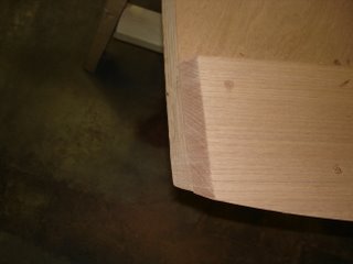
Finishing up the braces on the sides of the transom and motorwell. Cutting the curved bevel was simple using a Japanese pull saw with the hard sapele bevel as a guide. Couple of strokes with a plane made them flush.

Glueing up the stem


Spreading thickened epoxy on the strips, they;ve already been drenched in unthickened epoxy.


Big sloppy mess of strips clamped into place in the form. I waxed the clamping blocks and the plywood form very well, so the stem won;t stick to it.

Friday, October 27, 2006

Frames


Finally gotten all the floor frames cut out. After having to make several over again, I'm glad they're all done. All the notches for the stringers and the keel are cut as well. For the limber holes, I used a big forstner bit before I cut the tapers. Now to stick these on the strongback...

Starting on the center console

I'm going to put a center console on this boat. After much searching around, the console on a Jones Brothers Bateau is my model.


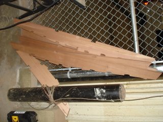
I took measurements off of this one and sketched out a design for mine. Here are the side panels cut out- they look small by themselves but as a whole it is a good size.


This is an example of how I'll put the console together. Using a 1 1/2" square piece of cedar, I cut a 3/4" by 1/2" slot on either corner to fit the 1/2" plywood. Then I roundover the corner with a router and get a very smooth, fiberglassed look.


I'm going to put the 18 gal Tempo tank underneath the front seat of the console. I'd rather not have the fill and vent inside the boat, but there is no other way to do it. I'm going to partition the tank off and isolate it from the electrical stuff at the back of the console. For the fill, I'm using a bronze combination fill/vent made by Perko- this will be less likely to spill fuel inside the boat.

I'll also get a stainless grab rail made like the one on the Jones Brothers and get some cushions made for the front seat. I'll put a large access hatch on the seat back to get to the wiring.

Transom/motorwell 2


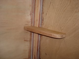
I've installed the shelf-like braces on the sides of the motorwell. I cut these out of scrap spanish cedar on the bandsaw- they turned out very well. I accidentaly screwed them perpendicularly to the motorboard; they should be parallel to the floor. Then finished dry fitting the motorwell to the transom. You have to make the pilot holes for screws very big when screwing into this rock hard sapele plywood. I''ve probably stripped out 25 screws.

Monday, October 09, 2006

Stem

I've run into a number of obstacles making the stem. I was origionally going to make it out of 10 strips of 3/8"x2 1/4" spanish cedar, but bending and clamping 3/8" strips proved suprisingly impossible. I'm not resawing them with a table saw to 1/4" thick, and using 15 instead of 10. They bend considerably easier, and as I understand it the more laminates the better. I had thought about steam bending the strips when they were still 3/8" thick, but resawing them is much simpler. I traced the stem pattern onto some cheap 11/2" ply and glued and screwed some clamping blocks to it. Once I get all the strips cut, I will slather them with thick epoxy and clamp them into the form. After curing, I'll cut the bevel.


Shown here are the 3/8" strips and the clamping jig

Transom/Motorwell


I cut my transom out of 3/4" BS1088 sapele- this is some nice stuff. Accidentally cut the top bevel too steep, but it will work out fine. Also shown are the sides of the motorwell. I haven;t cut out the arc yet. I widened the well a little on either side, as per recommendation by a number of Simmons builders.


With one layer of the motorboard attatched- it is built of two 3/4" layers and one 3/8" layer.


Here is the motorwell glued up. I used 2" by 3/4" braces in the corners, after doing that, I would have rather used a triangular piece to give the inside of the well a nicer look. I might epoxy a piece on there to accomplish that. I've been using a ProPrep scraper to smooth out cured epoxy fillets- it works great. Much easier than sanding, and it gives a very smooth finish. No breathing epoxy dust either.
The well/transom is fastened using silicon bronze screws and thickened epoxy.


Here is one of the braces on the inside of the transom. The lumber I'm using is spanish cedar. Once I get the other three made, I will epoxy and nail these to the transom, and then fasten the motorwell.

Strong back

I played around with several methods of making the strongback- and finally decided the best and simplest option would be to use a clear, dead straight 2x10.

I used MDF and 2x4 braces to hold the strong back up- it is level, stable, and sturdy. The notches for the frames are cut, but I have been improving them by adding blocks of MDF on wither side to ensure the right height and angle of the frames.